 Fig 1. Female slots
 Fig 1. Female slots
 Fig 2. Male pins
1. Pin/Slot 20 (arrowed above) may have an absent pin or be blanked of as a key identifier. It carries no data nor power.
2. The outside notch beside Pins/Slots 19 and 21 may or may not be present.
3. The ribbon cable normally has a red line going to Pin/Slot 1.
 Fig 3. Female Slots
 Fig 4. Male Pins
The first 40 are the same as their desktop cousins but there are an additional four pins (41 to 44) which use 5V power normally carried by a molex connector on a desktop hard drive.
Don't confuse the four pins (41 to 44) with another bank of four pins (- usually separated from the other 44 pins by a gap -) which are for jumpering the laptop hard drive. These are usually not jumpered at all on laptop hard drives.
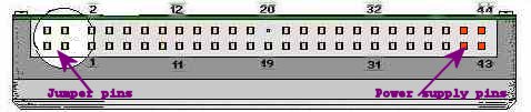 Fig 5. End-view of 2.5" drive - (PCB on top here).
The four-pin jumper block seldom actually has any jumpers on it and this is commonly the Master setting. There is however much variation and the drive itself should be examined carefully for the correct jumper settings or the internet browsed for supporting documentation for the make and model in question.
Dont confuse the above layout with the less commonly seen 60-pin blocks, where the first six pins are customisable and the last 44 are the same as the 44-pin ATA/Power layout as in Fig 5. The absent pin (if it is absent) for Key at posn 20 can often be very useful in orientation.
| Pin | Name | Dir | Description |
|---|---|---|---|
| 1 | /RESET | OUT | Reset |
| 2 | GND | ------ | Ground |
| 3 | DD7 | IN/OUT | Data 7 |
| 4 | DD8 | IN/OUT | Data 8 |
| 5 | DD6 | IN/OUT | Data 6 |
| 6 | DD9 | IN/OUT | Data 9 |
| 7 | DD5 | IN/OUT | Data 5 |
| 8 | DD10 | IN/OUT | Data 10 |
| 9 | DD4 | IN/OUT | Data 4 |
| 10 | DD11 | IN/OUT | Data 11 |
| 11 | DD3 | IN/OUT | Data 3 |
| 12 | DD12 | IN/OUT | Data 12 |
| 13 | DD2 | IN/OUT | Data 2 |
| 14 | DD13 | IN/OUT | Data 13 |
| 15 | DD1 | IN/OUT | Data 1 |
| 16 | DD14 | IN/OUT | Data 14 |
| 17 | DD0 | IN/OUT | Data 0 |
| 18 | DD15 | IN/OUT | Data 15 |
| 19 | GND | ------ | Ground |
| 20 | KEY | - | Key |
| 21 | n/c | - | Not connected |
| 22 | GND | ------ | Ground |
| 23 | /IOW | OUT | Write Strobe |
| 24 | GND | ------ | Ground |
| 25 | /IOR | OUT | Read Strobe |
| 26 | GND | ------ | Ground |
| 27 | IO_CH_RDY | IN | |
| 28 | ALE | OUT | Address Latch Enable |
| 29 | n/c | - | Not connected |
| 30 | GND | ------ | Ground |
| 31 | IRQR | IN | Interrupt Request |
| 32 | /IOCS16 | ? | IO ChipSelect 16 |
| 33 | DA1 | OUT | Address 1 |
| 34 | n/c | - | Not connected |
| 35 | DA0 | OUT | Address 0 |
| 36 | DA2 | OUT | Address 2 |
| 37 | /IDE_CS0 | OUT | (1F0-1F7) |
| 38 | /IDE_CS1 | OUT | (3F6-3F7) |
| 39 | /ACTIVE | OUT | Led driver |
| 40 | GND | ------ | Ground |
| 41 | +5VL | ----> | +5VC (Logic) |
| 42 | +5VM | -----> | +5VC (Motor) |
| 43 | GND | ------ | Ground |
| 44 | /TYPE | -----> | Type (0=ATA) |
80-wire data cables, when used, still only attach to pins 1 to 40. They are part of the UDMA (Ultra DMA) Transfer Mode specification of the ATA/ATAPI-4 standard. The extra wires are interposed between the original 40 wires and all run to earth to prevent stray signals crossing over between adjacent wires. This allows for faster trouble-free data transfer and automatically supports the CableSelect feature. The same standard allows for colour-coding of the connectors on the cable. Blue to motherboard, Grey (in the middle) to any Slave Drive and Black to the Master or to a Single Drive. Under the specification it is not allowable to attach a single drive to the middle connection.
More and more Solid State (NAND and CompactFlash) as well as Spinning 1.8" Hard Drives are coming on stream. These usually have a 50-pin interface for which we don't yet have the specifications. Some come with a ZIF (zero force clip on connections) and some with mini-ATA or micro-ATA 50 pin sockets. The latter can be quite easily interfaced using a 1.8"-to-2.5" converter. There is also an adapter to connect these small 1.8" drives inside a 2.5" USB external enclosure.